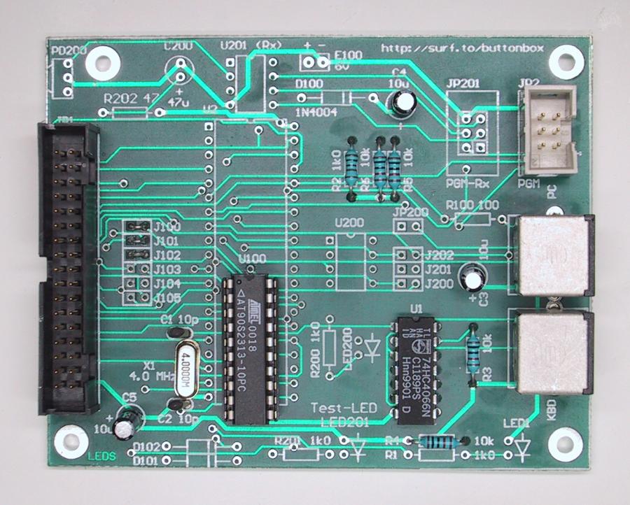
This is the the complete MiniBox board.
Hardware
So, what makes the MiniBox work? Actually it is a mini-version of the ButtonBox2, i.e. a small PCB containing a microprocessor and a couple of extra components to connect it to the PC and Keyboard.
The MiniBox can be built as just one unit, but as with the ButtonBox2 it can also be build as two separate units, a CPU-card and a Matrix connector-card. These two cards are then connected to each other using a standard 14-pin flat-cable. This allows for an easy way of switching between different arcade control panels, even without rebooting the PC. You have one CPU-card which is connected to the PC, then you can have several connector-cards, one for each arcade control panel.
The MiniBox differs a bit from the ButtonBox2 as it does not allow for connection of buttons in Direct mode, only Matrix mode is allowed. This comes from the fact that the AT90S2313 has fever I/O-ports. The number of I/O-ports on the AT90S2313 would only allow for connection of 12 buttons in Direct mode, and since that is a bit low, I decided not to include any Direct-mode support in the software (there is not enough room for it in the CPU anyway).
PCB
The PCB card for the MiniBox consists of a microprocessor from Atmel, an AT90S2313 (1.8MB pdf specification) running at 4 MHz. The processor includes 2kB flash memory for the program, 128 bytes EEPROM for configuration data and 128 bytes of RAM.
To this processor, a 74HC4066 is connected which is used to "disconnect" the ordinary keyboard from the PC when the MiniBox sends data to the PC.
|
|
This is the the complete MiniBox board. |
For those of you interested in how things are connected on the CPU-card, here is a logical drawing of it, and here is a pdf-file (11 kB) of the layout drawn in Protel-99.
Information about which components to mount on this general PCB to get a working MiniBox, is available in the "PCB"-section (look in the left frame).
Here is a list of components needed to build the MiniBox CPU-card:
| Item | # of pieces | Price | Total Price |
|---|---|---|---|
| Atmel AT90S2313 CPU | 1 | $5.00 | $5.00 |
| 74HC4066, Quad bilateral switch | 1 | $0.50 | $0.50 |
| 4.0 MHz crystal | 1 | $2.50 | $2.50 |
| 34-pin IDC connector | 1 | $5.00 | $5.00 |
| 6-pin IDC connector | 1 | $2.00 | $2.00 |
| 6-pin mini-DIN connector (female) | 2 | $3.50 | $7.00 |
| 10pF ceramic capacitor | 2 | $0.20 | $0.40 |
| 10µF electrolytic capacitor | 3 | $0.25 | $0.75 |
| 1kW resistor | 1 | $0.10 | $0.10 |
| 10kW resistor | 4 | $0.10 | $0.40 |
| Total price | $23.65 |
I am sure that it is possible to find the above components at a lower price, I just took the prices right out of the ELFA catalog and they are not always the cheapest to buy from.
Besides the components listed above you also need the following:
|
|
Something to build the thing on, for example a prototyping board |
|
|
A couple of IC-sockets if you don't want to solder directly on the IC's |
|
|
Some wire |
|
|
Soldering equipment |
Hopefully that's all you need to build one, if I have forgotten something, please tell me!
Connector-card
The connector-card for the MiniBox is a Matrix-card and looks very much like the Matrix-card for the ButtonBox2. The only difference is that it has only 32 inputs. This limitation comes from the fact that the AT90S2313 CPU has a limited number of inputs available. So 32 buttons was the max number we could squeeze in!
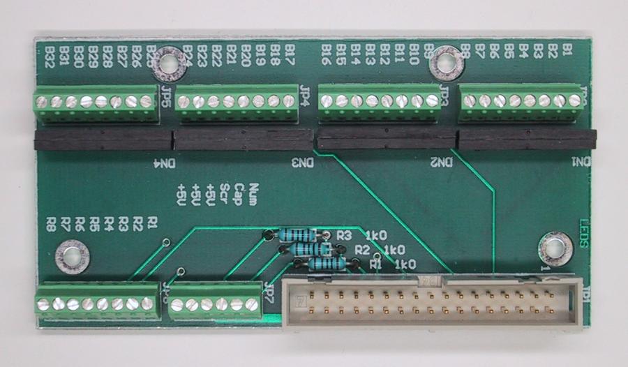 |
This is the MiniBox Matrix-card. |
Despite the fact that the MiniBox does not have support for the Caps-Lock, Num-Lock and Scroll-Lock indicators, we decided to make the PCB so that the connectors for these LED's could be added. That way, it is possible to add, the LED's (if you want them) and attach this 32-button Matrix-card too. But if you just want to use this card to the MiniBox, there is no use connecting the LED's they won't light up anyway.
The terminal-connectors you need for this card can be of any type, the ones I have used in this project are VERY expensive, but small. Bigger ones are much cheaper, so if you have enough space, use bigger ones.
Here is a pdf-file (8 kB) of the layout of the 32-button Matrix-card. It is drawn in Protel-99.
The MiniBox uses an 8x4 button-matrix which makes it possible to connect up to 32 buttons. Since a matrix is used to connect the buttons/joysticks to the MiniBox, the wiring of them is a bit more difficult. The MiniBox uses the same way as the ButtonBox2 (with the Matrix-card) to connect the buttons. Here is a logical drawing of how to connect the buttons to the MiniBox. One "side" of each button is connected to one of the terminal-connectors called "B1 - B32" on the logical drawing. The other "side" of the button is connected to one of the "row connector" terminals R1 - R8 in the following way:
| Button number | Row Connector |
|---|---|
| B1, B9, B17, B25 | R1 |
| B2, B10, B18, B26 | R2 |
| B3, B11, B19, B27 | R3 |
| B4, B12, B20, B28 | R4 |
| B5, B13, B21, B29 | R5 |
| B6, B14, B22, B30 | R6 |
| B7, B15, B23, B31 | R7 |
| B8, B16, B24, B32 | R8 |
That means that 4 buttons will be connected to the same "row connector" terminal.
Error indication
Since the MiniBox does not have a LED, it cannot give any indications if an error is discovered.