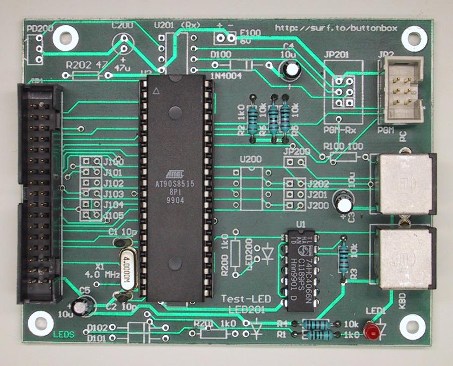
Here is a picture that shows the layout of the ButtonBox2 CPU-card.
This is built on a professionally made PCB (this picture shows the new "general" PCB).
(Click on the picture for larger view)
Hardware
So, what makes the ButtonBox2 do the thing it does? Basically it is a small PCB containing a microprocessor and a couple of extra components to connect it to the PC and Keyboard.
The ButtonBox2 is built as two separate units, the CPU-card and the connector-card. These two cards are then connected to each other using a standard 34-pin flat-cable (the same type which is used to connect floppy-drives to a PC motherboard, but not with the "twist" the floppy-cable has). This allows for an easy way of switching between different arcade control panels, even without rebooting the PC. You have one CPU-card which is connected to the PC, then you can have several connector-cards, one for each arcade control panel.
CPU-card
The CPU-card consists of a microprocessor from Atmel, a AT90S8515 (3.1MB pdf specification) running at 4 MHz. The processor includes 8kB flash memory for the program, 512 bytes EEPROM for key configuration data and 512 bytes of RAM.
To this processor, a 74HC4066 is connected which is used to "disconnect" the ordinary keyboard from the PC when the ButtonBox2 sends data to the PC.
|
|
Here is a picture that shows the layout of the ButtonBox2 CPU-card. This is built on a professionally made PCB (this picture shows the new "general" PCB). (Click on the picture for larger view) |
For those of you interested in how things are connected on the CPU-card, here is a logical drawing of it, and here is a pdf-file (11 kB) of the layout drawn in Protel-99.
Information about which components to mount on this general PCB to get a working ButtonBox2, is available in the "PCB"-section (look in the left frame).
Here is a list of components needed to build the ButtonBox2 CPU-card:
| Item | # of pieces | Price | Total Price |
|---|---|---|---|
| Atmel AT90S8515 CPU | 1 | $12.00 | $12.00 |
| 74HC4066, Quad bilateral switch | 1 | $0.50 | $0.50 |
| 4.0 MHz crystal | 1 | $2.50 | $2.50 |
| 34-pin IDC connector | 1 | $5.00 | $5.00 |
| 6-pin IDC connector | 1 | $2.00 | $2.00 |
| 6-pin mini-DIN connector (female) | 2 | $3.50 | $7.00 |
| 10pF ceramic capacitor | 2 | $0.20 | $0.40 |
| 10µF electrolytic capacitor | 3 | $0.25 | $0.75 |
| 1kW resistor | 2 | $0.10 | $0.20 |
| 10kW resistor | 4 | $0.10 | $0.40 |
| LED | 1 | $0.50 | $0.50 |
| Total price | $31.25 |
I am sure that it is possible to find the above components at a lower price, I just took the prices right out of the ELFA catalog and they are not always the cheapest to buy from.
Besides the components listed above you also need the following:
|
|
Something to build the thing on, for example a prototyping board |
|
|
A couple of IC-sockets if you don't want to solder directly on the IC's |
|
|
Some wire |
|
|
Soldering equipment |
Hopefully that's all you need to build one, if I have forgotten something, please tell me!
Connector-cards
The connector-cards can be built in two different ways, either a "direct-card" or a "matrix-card". The difference between these two cards is basically that the direct-card can connect up to 27 buttons, and the matrix-card can connect up to 128 buttons. Because of the extra components needed to build the matrix-card (except from extra connectors for the buttons), it is a little more expensive to build.
The direct-card
The direct-card is no more than a 34-pin IDC connector, 30 terminal-connectors, three resistors and three LED's. It is the easiest card to build, look here to view a logical drawing of it, and here to view a pdf-file (6 kB) of the layout drawn in Protel-99.
The LED's on the direct-card are used to represent the state of the Caps-Lock, Num-Lock and Scroll-Lock indicators on the ordinary keyboard. In order for these LED's to work as they are supposed to, the Atmel CPU has to have at least v1.01 of the ButtonBox2 code loaded.
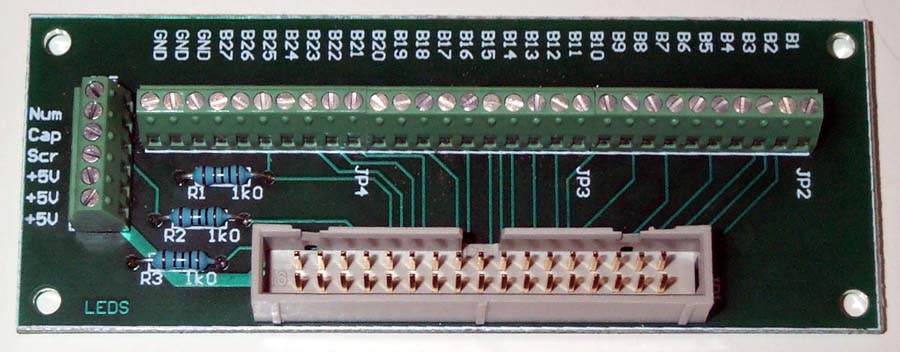 |
This is how the ButtonBox2 direct-card looks like. (Click on the picture for larger view) |
It is also very easy to understand how to connect the buttons to it. One "side" of each button is connected to one of the terminal connector B1 - B27. The other "side" of the button is connected to ground, which is on the three last terminal connectors. For a schematic picture of how to connect the buttons and LED's to the direct-card, look here.
The matrix-card
The matrix-card can be built in a number of different ways. Here I will explain how to build a 64-button (8x8 button-matrix), and a 128-button (8x16 button-matrix). The Matrix-card is a little harder to build since it includes a little more than the direct card. It contains a number of extra terminal-connectors for the buttons. It also contains a number of extra terminal-connectors, one (or two) for each "row" in the matrix, and a number of "8-in-one" diode arrays. These diodes are used to prevent keyboard "masking" and "ghosting". Here is a good explanation of the "masking" and "ghosting" problems that occur when a button-matrix is used without diodes.
The LED's on the matrix-card are used to represent the state of the Caps-Lock, Num-Lock and Scroll-Lock indicators on the ordinary keyboard. In order for these LED's to work as they are supposed to, the Atmel CPU has to have at least v1.01 of the ButtonBox2 code loaded.
 |
Here is how a 64-button
matrix-card looks like. The long, black "boxes" are the diode
arrays. Note that this picture has the
button-numbers wrong. As of v1.02 of the ButtonBox2 Atmel CPU-code, they
should be numbered from top to bottom as shown with red text.
(Click on the picture for larger view) |
It is a little more difficult to understand how to connect all the buttons to the matrix-card, but I'll try to explain how to do it. Look at this logical drawing of the matrix-card, or this for a pdf-file (8 kB) of the layout drawn in Protel-99. One "side" of each button is connected to one of the terminal-connectors called "B1 - B64" on the logical drawing. The other "side" of the button is connected to one of the "row connector" terminals R1 - R8 in the following way:
| Button number | Row Connector |
|---|---|
| B1, B9, B17, B25, B33, B41, B49, B57 | R1 |
| B2, B10, B18, B26, B34, B42, B50, B58 | R2 |
| B3, B11, B19, B27, B35, B43, B51, B59 | R3 |
| B4, B12, B20, B28, B36, B44, B52, B60 | R4 |
| B5, B13, B21, B29, B37, B45, B53, B61 | R5 |
| B6, B14, B22, B30, B38, B46, B54, B62 | R6 |
| B7, B15, B23, B31, B39, B47, B55, B63 | R7 |
| B8, B16, B24, B32, B40, B48, B56, B64 | R8 |
That means that 8 buttons will be connected to the
same "row connector" terminal.
If that description wasn't very clear, here
is a schematic picture of how to connect the 16 first buttons and the LED's to the
matrix-card.
If you want to build a 128-button Matrix-card, here is a pdf-file (12 kB) of the layout drawn in Protel-99. In order for the 128-button Matrix-card to work, the Atmel CPU has to have at least v1.02 of the ButtonBox2 code loaded. Below is a table explaining which "row connector" terminal R1 - R8 the buttons on the 128-button card must be connected to (the first 64 is the same as in the table above):
| Button number | Row Connector |
|---|---|
| B65, B73, B81, B89, B97, B105, B113, B121 | R1 |
| B66, B74, B82, B90, B98, B106, B114, B122 | R2 |
| B67, B75, B83, B91, B99, B107, B115, B123 | R3 |
| B68, B76, B84, B92, B100, B108, B116, B124 | R4 |
| B69, B77, B85, B93, B101, B109, B117, B125 | R5 |
| B70, B78, B86, B94, B102, B110, B118, B126 | R6 |
| B71, B79, B87, B95, B103, B111, B119, B127 | R7 |
| B72, B80, B88, B96, B104, B112, B120, B128 | R8 |
If you build a 128-button Matrix-card, buttons 65-128 are not configured by default. Since the graphical version of the button configuration program (Bbxgui.exe) only can configure the 64 first buttons, you have to use the ButtonBox Scripting Tool (Bbxscr.exe) to configure buttons 65-128.
It is possible to build Matrix-cards for the ButtonBox2 that has support for almost exactly the number of buttons that you need. Say that you would like to build a Matrix-card for the ButtonBox2 that has support for 78 buttons. Then you take the drawing for the 128-button Matrix-card and ignore the JP14-JP19 terminal connectors and the DN11-DN16 diode arrays (these are responsible for buttons 81-128). When the card is ready, you connect a wire between the B79 and the R7 terminal connectors (look at the tables above for info on which button number to connect to which "row connector"). This wire tells the ButtonBox2 that it should stop scanning the Matrix-card at button 78. This way the scanning of the buttons goes faster since the ButtonBox2 does not need to scan buttons 79-128, as they are not used (this means that for the 64-button Matrix-card above, a wire has to be connected between B64 and R8. Otherwise the ButtonBox2 will scan all 128 buttons. So the 64 button Matrix-card is actually only able to support 63 buttons).
Error indication
There are some situations where the ButtonBox2 software encounters situations that can be of interest to the user. For this reason there is a LED mounted on the CPU-card.
 |
During normal operation, the LED flickers very fast. If it stops flickering, then the ButtonBox2 has stopped for some reason (I have never seen this happen). |
When an error (it's not really an error, but we call them that here) is encountered, the LED starts to blink in a way that can be decoded by the user as an error-code. The error code is presented to the user as a four bit number, each bit represented by a short blink (bit = 0) or a long blink (bit = 1) on the LED.
So, error-code 1 makes the LED blink like this:
 |
long (lsb) - short - short - short (msb) - pause, repeat again. This makes the binary pattern '0001', which is the decimal number 1. |
This error-code will continue to blink until one of the following things occur:
Here is a table that explains the existing error-codes:
| Error code | Description of error |
|---|---|
| 1 | "Set Scan Set 1" received, which isn't supported by the ButtonBox2. |
| 2 | "Set Scan Set 3" received, which isn't supported by the ButtonBox2. |
| 3 | "Default Disable" received. Ignored by ButtonBox2, but displayed as information to user. |
| 4 | "Set All Keys - Typematic" received. Affects only Scan Set 3, ignored by ButtonBox2. |
| 5 | "Set All Keys - Make/Break" received. Affects only Scan Set 3, ignored by ButtonBox2. |
| 6 | "Set All Keys - Make" received. Affects only Scan Set 3, ignored by ButtonBox2. |
| 7 | "Set All Keys - Typematic/Make/Break" received. Affects only Scan Set 3, ignored by ButtonBox2. |
| 8 | "Set Key Type - Typematic" received. Affects only Scan Set 3, ignored by ButtonBox2. |
| 9 | "Set Key Type - Make/Break" received. Affects only Scan Set 3, ignored by ButtonBox2. |
| 10 | "Set Key Type - Make" received. Affects only Scan Set 3, ignored by ButtonBox2. |
| 11 | "Resend" received. Ignored by ButtonBox2 at the moment. |
| 15 | The ButtonBox2 has been instructed by the PC (in an unusual way) to stop sending and retry later. |